

Compare CNC Milling vs CNC Turning in cost, tolerances, applications, and speed. Learn when to use each process or combine both with Lava3DP. Contact our machining experts for a free DFM review today!
In modern subtractive manufacturing, selecting the optimal CNC machining process dictates product quality, cycle time, and bottom-line manufacturing costs. Design engineers and procurement managers face a recurring decision when moving from CAD models to finished hardware: CNC milling vs CNC turning. Both methods fall under the umbrella of computer numerical control (CNC) machining, yet they operate on opposite kinematic principles.
Choosing between a CNC milling machine and a CNC lathe impacts part geometry, dimensional accuracy, surface roughness, and overall unit price. Understanding these technical distinctions ensures your components meet engineering specifications without driving up production costs.
CNC Milling vs CNC Turning Comparison Table
| Attribute | CNC Milling | CNC Turning |
| Primary Motion | Rotating cutting tool | Rotating workpiece |
| Optimal Part Geometry | Prismatic, flat, complex, asymmetrical | Cylindrical, round, tubular, rotationally symmetric |
| Tooling Used | End mill, face mill, drills, slot cutters | Single-point turning tools, boring bars, threading inserts |
| Workholding | Vises, fixtures, T-slot tables, vacuum plates | Chuck, collet, tailstock, steady rest |
| Standard Precision | ±0.001 in (0.025 mm) to ±0.0002 in (0.005 mm) | ±0.0005 in (0.013 mm) to ±0.0001 in (0.0025 mm) |
| Surface Roughness | 32 to 125 µin Ra (0.8 to 3.2 µm Ra) | 16 to 63 µin Ra (0.4 to 1.6 µm Ra) |
| Material Removal Rate | Variable (high for heavy pocketing) | High and continuous for external diameters |
| Primary Cost Driver | Setup time, multi-axis motion, tool changes | Tool wear, raw bar stock diameter, setup time |
Key Difference Between Milling and Turning
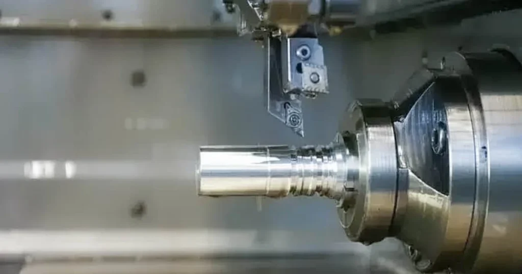
The fundamental difference between CNC turning and milling lies in which element moves during material removal. In milling vs turning, milling uses a rotating cutting tool that travels across a stationary workpiece to shear away stock. In turning vs milling, the process reverses: a chuck or collet clamps a rotating workpiece while a stationary single-point cutting tool feeds into the material along linear axes.
This core kinematic difference determines part shape suitability. Milling handles flat surfaces, pockets, complex curves, and prismatic geometries. Turning excels at concentric profiles, threads, grooves, and cylindrical features.
Related: Aluminum CNC Machining: Complete Guide to Processes, Grades, Service Costs & Design Tips (2026)
What Is CNC Milling?
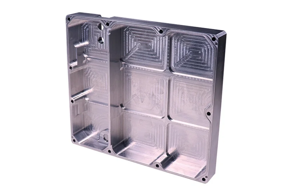
CNC milling serves as one of the most versatile subtractive manufacturing processes in precision engineering. Machinists rely on CNC milling for flat parts, complex structural brackets, molds, and housings that require multi-directional material removal.
How CNC Milling Works
The CNC milling process begins with securing a solid block of metal or plastic onto a stationary machine bed or fixture. A high-speed spindle holds the tool and rotates at speeds reaching 10,000 to 30,000 RPM. Guided by G-code programs generated from 3D CAD files, the rotating cutter traverses along multiple axes (X, Y, and Z) to strip away material layer by layer.
During cutting, coolant flushes the contact zone to mitigate tool wear, control heat generation, and clear metal chips from the cut path. Advanced tool access paths optimize the material removal rate while minimizing tool deflection, ensuring high dimensional accuracy across deep pockets or thin walls.
Common CNC Milling Operations
Modern machining centers perform diverse operations using tailored tool geometries:
- Face Milling: Uses large-diameter cutters to flatten large top surfaces, achieving high flatness and smooth surface roughness.
- End Milling: Employs end mills with cutting edges on the sides and bottom to cut deep pockets, slots, outer contours, and stepped profiles.
- Drilling and Tapping: Creates precise vertical holes and internal threads using twist drills, spot drills, and thread mills.
- Slotting and Pocketing: Clears internal cavity volumes while holding strict positional accuracy relative to datum faces.
3-Axis, 4-Axis & 5-Axis CNC Milling
Machine complexity dictates geometric capabilities:
- 3-Axis CNC Milling: The tool moves along X, Y, and Z axes. It works well for simple flat parts, planar cutouts, and shallow pockets, but requires manual re-fixturing to machine multiple sides.
- 4-Axis CNC Milling: Adds a rotary A-axis (usually around the X-axis). This setup allows indexing and continuous cutting around cylindrical surfaces or angled features without manual resets.
- 5-Axis CNC Machining: Adds rotary motion along two axes (A/B or B/C). The machine tilts and rotates either the spindle or the table simultaneously. This provides maximum tool access to cut highly complex parts, deep cavities, and compound angles in a single machine setup.
What Is CNC Turning?
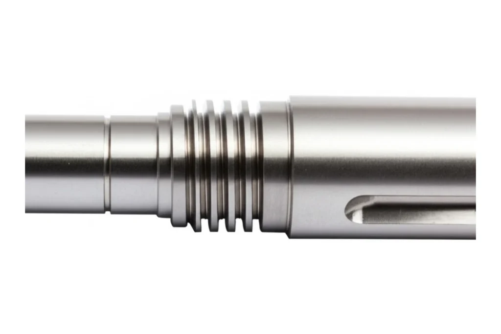
CNC turning dominates the production of round, symmetrical hardware. From simple steel pins to complex stepped driveshafts, turning delivers unmatched roundness and concentricity.
How CNC Turning Works
In CNC turning, a spindle drives a chuck or collet to spin a cylindrical raw bar at high RPMs. A rigid tool turret positioned adjacent to the workpiece holds stationary single-point cutting tools.
As the bar rotates, the tool turret feeds the cutting tool horizontally along the Z-axis (parallel to the bar) or radially along the X-axis (into the diameter). The continuous contact between the non-rotating tool and the rotating bar pares down external diameters, bores inner diameters, and faces off ends with extreme speed and repeatability.
Common CNC Turning Operations
CNC turning handles a wide range of external and internal axial profiles:
- Facing: Trims the end face perpendicular to the rotation axis, establishing exact part length and flat reference datum faces.
- O.D. and I.D. Turning: Reduces the outer diameter (O.D.) or opens up an internal bore (I.D.) to hit precise diametrical tolerances.
- Grooving and Cut-Off (Parting): Cuts narrow radial channels into the part or severs the finished turned component from the main bar stock.
- Threading and Boring: Generates exact internal or external screw threads or enlarges existing holes while enforcing strict concentricity and cylindricity.
CNC Lathe vs CNC Turning Center
While technicians frequently use the terms interchangeably, subtle machine differences exist between a basic CNC lathe and an advanced turning center:
- CNC Lathe: Typically features a simple 2-axis setup (X and Z) with an open or semi-enclosed bed, suited for straightforward turned parts, manual short-run work, or basic repairs.
- Turning Center: Incorporates full machine enclosures, chip conveyors, automatic tool changers, sub-spindles, live tooling capabilities, and 3 to 5 axes of motion. Turning centers handle high-volume, automated production with zero manual intervention.
CNC Milling vs CNC Turning: Key Differences
Evaluating CNC machining milling vs turning requires examining how tool kinetics influence part quality, setup overhead, and production cycle times.
Cutting Tool and Workpiece Movement
The foundational contrast remains motion dynamics:
- Milling: Rotating cutting tool + stationary workpiece.
- Turning: Rotating workpiece + stationary cutting tool.
Because turning features uninterrupted, continuous contact between tool and material, it generates steady cutting forces. Milling utilizes interrupted cutting—each cutter tooth engages and disengages material hundreds of times per minute. This interrupted engagement creates micro-vibrations and mandates rigid machine setups to control tool wear and tool deflection.
Part Geometry and Design
Part shape dictates process selection immediately:
- Prismatic Parts: Square blocks, rectangular brackets, engine heads, and electronic enclosures with flat faces or complex internal pockets require CNC milling for complex parts.
- Cylindrical Parts: Shafts, bushings, flanges, fasteners, and threaded couplings demand CNC turning for cylindrical parts with strict rotational symmetry.
Machining Setup and Tool Access
Setting up a CNC machine influences overall part cost:
- Workpiece holding on a mill involves vises, soft jaws, or custom fixtures. Complex 3-axis parts often require three to five separate manual setups to machine every face, increasing labor costs.
- Turning uses standardized 3-jaw chucks or spring collets. Bar feeders can automatically push raw material through the spindle bore, allowing long automated runs with minimal setup overhead.
Accuracy, Tolerances and Surface Finish
Both processes yield high-precision parts, but turning holds a mechanical advantage for diametrical features:
- CNC Milling Accuracy: Holds dimensional tolerances around ±0.0005 in (0.013 mm). Achieving smooth Ra surface finish on milled flat faces depends on tool stepover distance, which leaves subtle step marks (cutter scallops).
- CNC Turning Accuracy: Holds tight CNC turning tolerances down to ±0.0001 in (0.0025 mm). Because the single-point tool stays in continuous contact with the smooth, rotating bar, turning routinely yields superior surface roughness (16–32 µin Ra) without secondary grinding.
Production Speed and Cycle Time
For round geometries, turning removes material significantly faster than milling. A turning tool strips large bar volumes in continuous linear passes. Milling must clear material through circular tool paths, corner slowdowns, and multiple tool swaps, which inflates cycle time on round profiles.
Related: Rapid Tooling: Complete Guide to Prototype Tooling, Bridge Molds & Rapid Injection Molding (2026)
CNC Milling vs CNC Turning: Cost Comparison
Controlling procurement expenditure requires understanding how machine shop rates, tooling setups, and operational parameters influence the final CNC machining cost comparison.
CNC Milling Cost Factors
Milling costs climb when designs demand extensive machine programming, specialized cutters, or multi-axis movements. Deep pockets require slow feed rates to prevent tool deflection, extending cycle times. Machining multiple part faces on 3-axis equipment multiplies manual fixture swaps and setup labor charges.
CNC Turning Cost Factors
Turning features lower setup costs for standard round bar stock. Cost increases when turning requires large-diameter specialty alloys or exceptionally long slender shafts that require steady rests to prevent deflection. Deep small-diameter internal boring operations can also elevate cycle times due to chip clearance challenges.
Setup, Tooling, Material and Labor Costs
Evaluating overall CNC milling cost vs turning cost breaks down into four main variables:
- Setup Costs: Milling fixtures and multi-vise setups require time-consuming alignment. Turning chucks and collets swap rapidly, lowering initial setup fees.
- Tooling Costs: Milling end mills, face mills, and specialized profile cutters cost significantly more than replaceable carbide turning inserts.
- Material Utilization: Turning starting stock (round bar) often matches the near-net shape of round parts, minimizing scrap. Milling carves components out of oversized square billets, creating higher raw material waste.
- Labor Overhead: Turning paired with automatic bar feeders supports unattended (“lights-out”) production. Milling frequently requires operators to flip parts manually across multiple setups.
Which Process Is More Cost-Effective?
Is CNC milling cheaper than turning, or is CNC turning cheaper than milling?
Generally, CNC turning stands as the most cost effective CNC machining process for any component defined by rotational symmetry. For flat, square, or irregular hardware, CNC milling proves more cost-effective because turning non-symmetric parts causes severe rotational imbalance and tool chatter.
CNC Milling vs CNC Turning: Tolerances and Precision
Meeting geometric dimensioning and tolerancing (GD&T) specifications requires choosing the process best aligned with your dimensional target.
CNC Milling Tolerances
Standard CNC milling tolerances sit at ±0.001 in (0.025 mm) for standard features and ±0.0002 in (0.005 mm) on precision machining centers. Achieving high positional accuracy across distant hole patterns or maintaining tight flatness across large plates depends on machine thermal stability and rigid workholding.
Key milling tolerance drivers include:
- Flatness & Parallelism: Easily maintained on top faces using sharp face mills.
- Positional Accuracy: Depends on ball screw calibration along X, Y, and Z axes.
- Corner Radii: Internal vertical corners inherit the radius of the rotating end mill, preventing sharp 90-degree internal square corners.
CNC Turning Tolerances
Standard CNC turning tolerances routinely reach ±0.0005 in (0.013 mm), with high-precision turning centers holding ±0.0001 in (0.0025 mm).
Turning excels in these GD&T parameters:
- Concentricity: Turning internal and external diameters in a single chuck clamping ensures absolute axial alignment.
- Cylindricity & Roundness: High spindle rotational precision produces near-perfect round profiles.
- Surface Finish: Micro-finishes under 16 µin Ra are easily achieved, eliminating external grinding steps.
Choosing the Right Process for Critical Dimensions
When part prints specify strict concentricity between inner and outer diameters, select turning. If the drawing calls out absolute flatness, squareness, or intricate hole-pattern locations across a 3D block, choose milling.
Related: Laser Cutting Services: Process, Materials, Tolerances, Design Guide, Applications & Cost (2026)
CNC Milling vs CNC Turning: Materials
Material machinability varies based on whether cutting forces are continuous or interrupted.
Aluminum CNC Machining
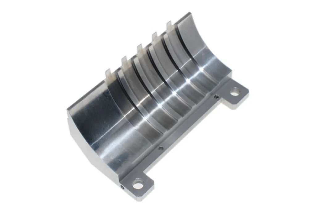
Aluminum (6061-T6, 7075-T6) cuts cleanly across both processes. Its light weight, excellent thermal conductivity, and rapid material removal rate make it the default standard for prototype machining and production runs. High spindle speeds on mills easily shear aluminum without heavy tool wear.
Stainless Steel and Steel Machining
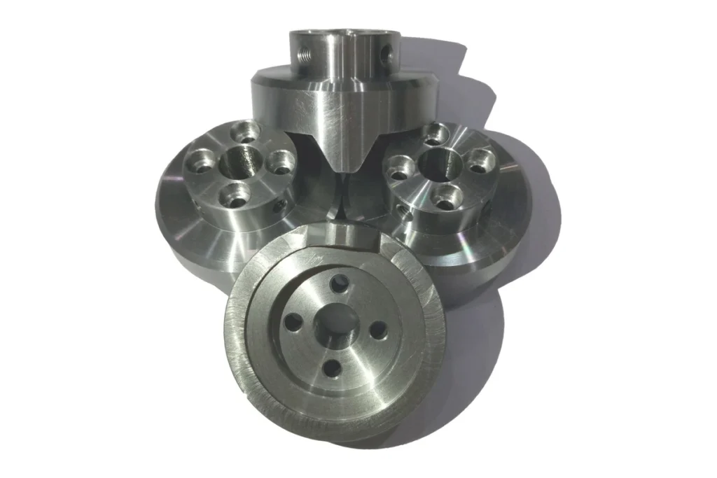
Stainless steels (304, 316, 17-4PH) and alloy steels (4140, 4340) exhibit high strength and work-hardening tendencies. Turning handles tough steels effectively because continuous cutting chips prevent work-hardening the metal ahead of the tool. Milling stainless requires heavy rigid setups and active coolant flow to control thermal stress on cutter teeth.
Brass and Copper Machining
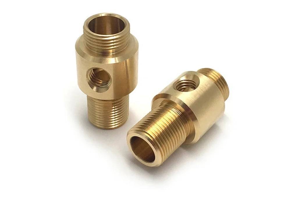
Free-cutting brass (C36000) machines exceptionally fast with minimal tool wear, making it ideal for high-speed turned fittings and electrical connectors. Pure copper presents higher ductility, requiring sharp tool geometry in both milling and turning to prevent material smearing and heavy burr formation.
Titanium CNC Machining
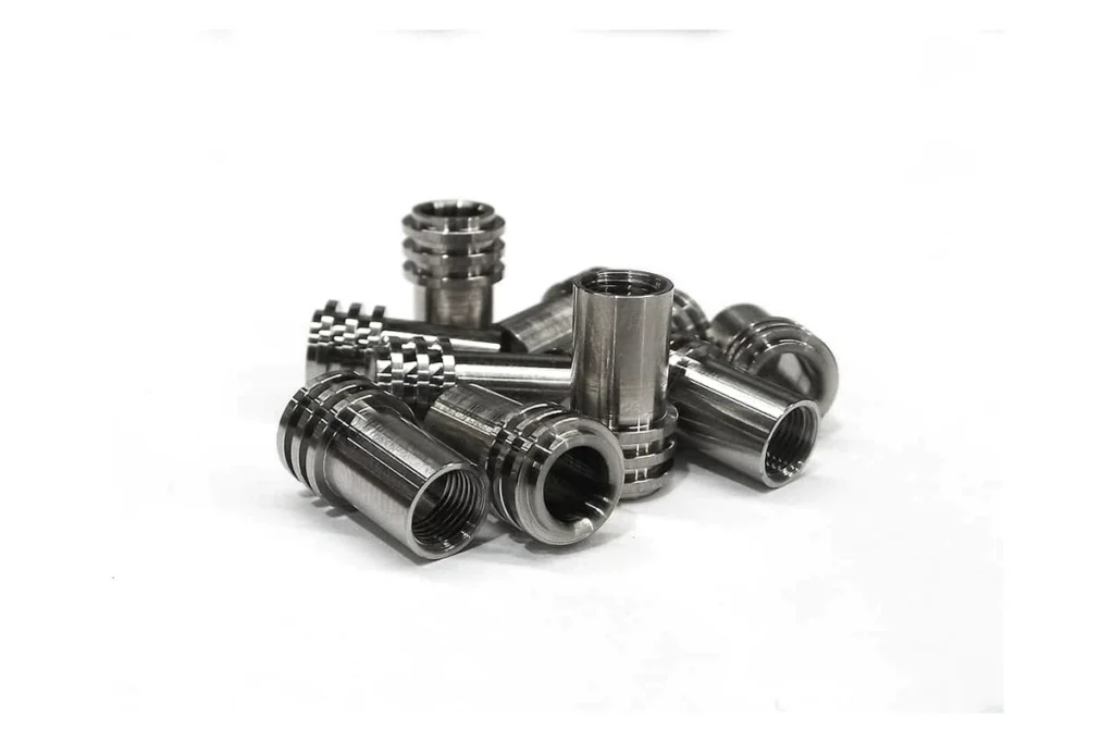
Titanium (Grade 5 / Ti-6Al-4V) features low thermal conductivity and high elasticity. Heat accumulates at the cutting edge rather than dissipating into the chip. Turning titanium requires low RPMs, heavy feed rates, and high-pressure coolant. Milling titanium demands rigid multi-flute end mills and high dynamic tool paths to avoid chatter and sudden tool breakage.
Engineering Plastics CNC Machining
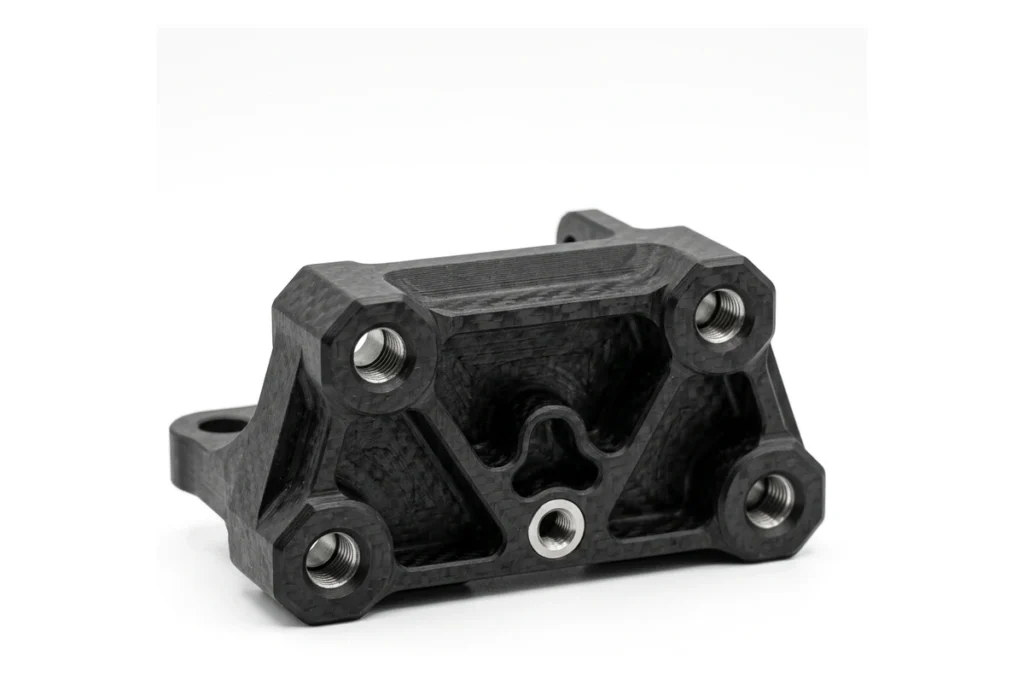
Plastics like POM (Delrin), PTFE, PEEK, and ABS cut quickly on both turning centers and mills. Operators must manage heat buildup to prevent plastic softening, melting, or surface warping. Sharp tools with positive rake angles ensure clean chip clearance in turned sleeves or milled plastic manifolds.
CNC Milling vs CNC Turning: Applications
Both operations supply essential hardware across critical global supply chains.
CNC Milling Applications
Milling yields complex, non-cylindrical structures across major industries:
- Aerospace: Ribbed wing spars, structural bulkheads, turbine housings, and bracketry.
- Automotive: Engine blocks, gearbox covers, intake manifolds, and custom suspension arms.
- Robotics: Servo mounts, structural chassis plates, and articulated robot arm joints.
CNC Turning Applications
Turning delivers high-precision rotational hardware:
- Medical: Surgical bone screws, dental implants, orthopedic pins, and syringe barrels.
- Electronics: Coaxial connectors, threaded standoff pins, knob dials, and sensor bodies.
- Industrial: Hydraulic valve spools, threaded pipe fittings, pump impellers, and drive shafts.
Aerospace, Automotive and Robotics Parts
Aerospace and automotive hardware frequently demands both strength and light weight. Multi-axis milling hollows out solid metal blocks into thin-walled, high-strength structural ribs. Robotics relies heavily on milled aluminum joints paired with turned precision drive shafts and internal bearing sleeves.
Medical, Electronics and Industrial Components
Medical devices require extreme bio-compatibility and ultra-smooth surface finish. Titanium turned fasteners and bone pins fit these requirements perfectly. Electronics manufacturers combine turned brass jack posts with milled heat sinks to optimize thermal dissipation and electrical connectivity.
Related: Full Color 3D Printing Services: Technologies, Pricing & Design Guide (2026)
When Should You Choose CNC Milling or CNC Turning?
Selecting the optimal production route relies on clear engineering rules based on part shape, features, and production volumes.
Choose CNC Milling for Complex and Prismatic Parts
Opt for CNC milling when your component design incorporates:
- Flat surfaces, mounting faces, and stepped ledges.
- Internal square or curved pockets, cavities, and complex contours.
- Off-center drilled holes, tapped patterns, and counterbores.
- Non-symmetrical prismatic geometries that cannot spin safely in a lathe chuck.
Choose CNC Turning for Cylindrical and Rotational Parts
Opt for CNC turning when your component design features:
- Complete rotational symmetry around a central longitudinal axis.
- External or internal precision screw threads.
- Concentric outer diameter steps, tapers, or deep radial grooves.
- Requirements for high roundness, concentricity, and smooth micro-surface finishes.
When Both Milling and Turning Are Required
Many complex parts feature both round bodies and flat features—such as a cylindrical driveshaft with a flat keyway, radial oil holes, or square flange mounting holes. Traditionally, machine shops turned the main cylindrical body on a lathe first, then transferred the part to a mill for secondary operations. Today, modern mill-turn equipment bridges this divide.
Mill-Turn Machining: Combining CNC Milling and Turning
Mill-turn machining blends the rotational speed of turning with the geometric flexibility of multi-axis milling inside a single machine envelope.
What Is CNC Mill-Turn Machining?
CNC mill-turn machining uses a high-powered turning center fitted with live tooling—spindles mounted directly on the tool turret that drive rotating end mills, drills, and taps. As the workpiece spins or indexes along a controllable C-axis, the live tools perform side-milling, cross-drilling, keyway slotting, and off-center pocketing without removing the part from the chuck.
Benefits of Combining Milling and Turning
Adopting CNC turning and milling combination platforms yields significant engineering advantages:
- Done-in-One Processing: Completes complex hardware in a single clamping setup.
- Enhanced Positional Accuracy: Eliminates human orientation errors introduced during manual fixture swaps between separate lathes and mills.
- Reduced Cycle Times: Eliminates queues and material staging between separate machine departments.
Mill-Turn vs Separate CNC Milling and Turning Operations
While a CNC mill turn vs CNC turning center costs more initially, it eliminates labor fees for secondary milling operations. When evaluating when to use mill turn machining, compare total setup times: if secondary milling setups on a turned part exceed 20% of total processing time, mill-turn machining saves money overall.
Related: The Ultimate Guide to Rapid Prototyping: Processes, Materials, Costs & Applications (2026)
CNC Milling vs CNC Turning for Prototypes and Production
Production volume impacts machine selection, tooling amortizations, and design for manufacturability (DFM) strategies.
Prototype and Low-Volume CNC Machining
For initial prototype machining (1 to 10 parts), setup speed drives total cost. Turning centers require minimal physical fixture prep for round stock, keeping short-run prices low. Milling prototypes requires cutting custom soft jaws or configuring modular vises, which slightly increases unit costs for early-stage engineering iterations.
High-Volume Production
In mass production (1,000+ units), cycle time reduction dominates manufacturing economics. Bar-fed turning centers execute continuous automated production cycles with minimal operator oversight. Multi-spindle mill-turn machines manufacture high-volume automotive and medical hardware rapidly, driving down unit overhead.
Design for Manufacturability (DFM) Considerations
Implementing DFM guidelines early prevents costly manufacturing revisions:
- For Turned Components: Avoid deep narrow internal grooves that require custom tool ground bits. Maintain standard radius undercuts at internal shoulders.
- For Milled Components: Avoid internal sharp vertical corners; design internal pocket radii to accommodate standard end mill diameters. Limit pocket depth to under 4x tool diameter to prevent tool deflection and chatter.
CNC Milling vs CNC Turning: Which Is Better?
Determining which process is better CNC milling or turning depends strictly on your design requirements. Neither process is universally superior; each excels in its native geometric domain.
Best Process Based on Part Geometry
- Winner for Round/Cylindrical Shapes: CNC Turning.
- Winner for Boxy/Prismatic/Complex Shapes: CNC Milling.
Best Process Based on Tolerance and Surface Finish
- Winner for Concentricity & Diametrical Precision: CNC Turning.
- Winner for Flatness & Positional Hole Pattern Accuracy: CNC Milling.
Best Process Based on Cost and Production Volume
- Winner for Low-Cost Round Parts: CNC Turning.
- Winner for Low-Cost Flat Brackets: CNC Milling.
- Winner for Integrated Complex Components: Mill-Turn Machining.
Custom CNC Milling and CNC Turning Services from Lava3DP
At Lava3DP, we provide advanced, multi-axis custom precision manufacturing tailored to your exact engineering tolerances. Our automated machine shop pairs state-of-the-art CNC equipment with expert DFM analysis to deliver production-grade components fast.
CNC Milling for Custom Precision Parts
Our milling facility operates modern 3-axis, 4-axis, and 5-axis CNC machining centers capable of holding strict tolerances down to ±0.0002 in (0.005 mm). We machine complex prismatic brackets, thin-walled aerospace housings, and high-precision electronic enclosures out of solid alloy billets.
CNC Turning for Cylindrical Components
Lava3DP’s turning department features high-speed CNC turning centers with automatic bar feeders and live tooling options. We manufacture turned pins, threaded shafts, precision bushings, and custom fittings with exceptional concentricity and surface finishes reaching 16 µin Ra.
CNC Machining Materials and Surface Finishes
We stock a broad range of production materials, including aluminum, stainless steel, tool steel, brass, copper, titanium, and engineering plastics (POM, PEEK, PTFE). Enhance your parts with our full range of post-processing options:
- Anodizing (Type II & Type III Hardcoat)
- Passivation and Electropolishing
- Bead Blasting and Powder Coating
- Black Oxide, Plating, and Custom Laser Engraving
CAD Upload, DFM Review and Custom Production
Streamline your custom production with Lava3DP. Upload your 3D CAD files (STEP, IGES, or native formats) to receive a fast, competitive quote along with an expert Design for Manufacturability (DFM) review. Our engineering team inspects your drawings to optimize tool access paths, reduce cycle times, and lower your overall manufacturing costs.
Frequently Asked Questions About CNC Milling vs CNC Turning
What is the main difference between CNC milling and CNC turning?
The main difference between CNC turning and milling is workpiece movement. In CNC milling, a high-speed rotating cutting tool moves across a stationary clamped block to remove material. In CNC turning, the workpiece rotates continuously while a stationary single-point cutting tool feeds into the material to shape cylindrical profiles.
Is CNC milling more expensive than CNC turning?
CNC milling is generally more expensive than CNC turning for equivalent-sized parts due to higher tooling costs, longer cycle times, and complex workholding setups. However, for non-cylindrical prismatic components, milling remains the most practical and cost-effective manufacturing choice.
Which is more accurate, CNC milling or CNC turning?
Both processes deliver high precision, but CNC turning typically holds tighter diametrical tolerances (down to ±0.0001 in / 0.0025 mm) and superior surface roughness on round profiles. CNC milling excels at maintaining high positional accuracy and flatness across complex 3D surfaces.
Is CNC turning better for cylindrical parts?
Yes, CNC turning for cylindrical parts provides optimal geometric roundness, tight concentricity, and smooth surface finishes far faster than a milling machine can achieve through circular interpolation paths.
Can one CNC machine perform both milling and turning?
Yes, modern mill turn machining platforms combine a turning spindle with live rotating tooling on the turret. This single machine executes turning, cross-drilling, keyway milling, and tapping in a single automated setup.
How do I know whether my part needs CNC milling or CNC turning?
Evaluate your component’s core geometry: if the part is primarily round, tubular, or symmetrical along an axis, choose CNC turning. If the part features flat faces, deep pockets, internal cutouts, or non-symmetrical features, select CNC milling. For hybrid parts with both round and flat features, request a DFM review from Lava3DP to determine whether multi-axis milling or mill-turn machining yields the best manufacturing value.