

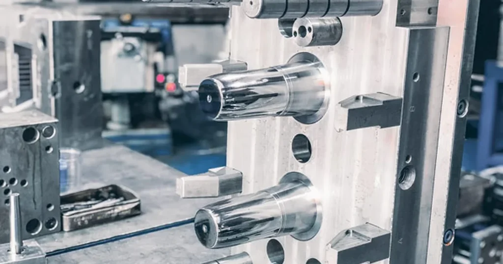
Master Rapid Tooling, prototype tooling, and Bridge Tooling to cut manufacturing lead times and costs. Get expert DFM tips, material specs, and quick quotes today at Lava3DP!
What Is Rapid Tooling?
Rapid Tooling Definition
Rapid tooling refers to any manufacturing method that creates mold inserts, cavities, or full mold assemblies quickly using direct or indirect digital manufacturing technologies. Unlike traditional mold making—which relies heavily on manual machining and weeks of EDM block preparation—this approach uses advanced CNC milling, additive techniques, and modular tooling frameworks to produce mold components in a fraction of the time.
How Rapid Tooling Accelerates Product Development
Speed defines modern engineering. By paring down mold design to essential geometry and using pre-machined master mold bases, rapid tooling shortens mold fabrication cycles from eight weeks to five days. Engineers receive real injected molded parts for functional testing early in the design phase, avoiding costly downstream changes.
Why Manufacturers Choose Rapid Tooling
Traditional production molds require massive upfront capital, often running into tens of thousands of dollars. Rapid tooling slashes initial expenditures while maintaining material integrity. It gives engineering teams access to true production-grade resins without committing to high-volume hard tooling.
When Rapid Tooling Is the Best Manufacturing Solution
Choose this process when you need between 50 and 10,000 plastic parts for market testing, clinical trials, or interim assembly line validation before high-volume steel tools are ready.
How Rapid Tooling Works
CAD Design and Design for Manufacturability (DFM)
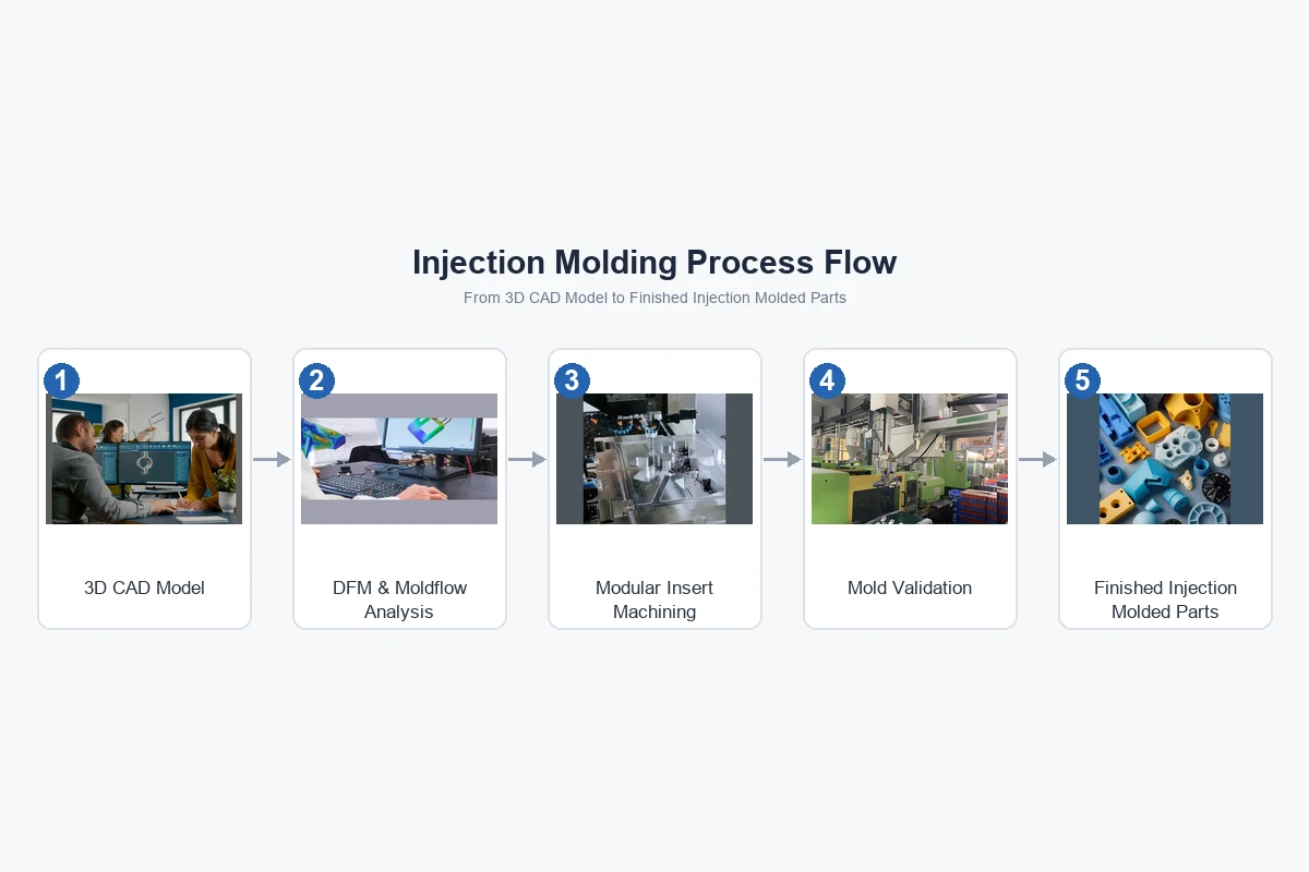
The workflow starts with a 3D CAD model. Automated DFM analysis software scans the geometry for thick walls, sharp internal corners, and improper draft angles, flagging potential issues like sink marks or ejection binding before cutting metal.
Tool Design and Mold Engineering
Engineers design a streamlined mold layout. To save time, standard interchangeable mold bases (MUD frames) house custom-cut mold inserts and mold cavities, focusing custom machining strictly on the part geometry.
Tool Manufacturing Methods
Machinists cut aluminum or soft steel inserts via high-speed CNC milling or print metallic components directly via Selective Laser Melting (SLM).
Mold Validation and Sampling
Once assembled, the mold goes to a press for T1 sampling. Technicians run initial shots to verify dimensions, optimize injection pressure, adjust cooling channels, and tune cycle times.
Production and Quality Inspection
After approving T1 samples, short-run production starts. Parts undergo CMM measuring, visual surface analysis, and functional checks before shipping.
Related: Insert Molding: Complete Design Guide, Process, Materials, Advantages & Cost (2026)
Types of Rapid Tooling
Direct Rapid Tooling
Direct tooling creates the actual mold inserts or cavities straight from CAD data using CNC machining or metal 3D printing. It delivers high geometric accuracy and structural strength for demanding resins.
Indirect Rapid Tooling
Indirect methods use a master pattern (often printed via stereolithography) to cast a secondary tool, such as a silicone or epoxy mold. This strategy works well for low-force casting or ultra-low-volume injection runs.
Soft Tooling
Soft Tooling relies on softer metals like 7075-T6 aluminum or silicone rubbers. It reduces machining times and tooling costs significantly, though it yields a shorter overall mold lifespan.
Hard Tooling
Hard tooling uses pre-hardened steels like P20 or NAK80. While it requires more machining time than aluminum, it withstands higher injection pressures, abrasives, and higher part quantities.
Hybrid Tooling Solutions
Hybrid systems pair 3D-printed metal inserts for complex internal cooling channels with standard CNC-machined aluminum plates, balancing cost, thermal performance, and build speed.
Prototype Tooling Explained
What Is Prototype Tooling?
A prototype injection mold focuses on speed and design verification rather than long-term durability. A prototype tooling company uses simplified ejector systems, manual loose inserts, and aluminum cavity plates to cut prototype tooling cost and delivery times.
Advantages of Prototype Tooling
- Ultra-Fast Turnaround: Parts in hand in 5 to 10 days.
- Low Financial Risk: Inexpensive modifications if part geometry changes.
- Real Resins: Uses actual production-grade polymers (e.g., ABS, PC, PEEK) rather than 3D printing approximations.
Limitations of Prototype Tooling
- Manual Interventions: Often uses hand-loaded inserts, slowing down cycle times.
- Lower Tool Longevity: Limited to 100–5,000 shots.
Ideal Applications
Perfect for functional prototypes, design validation, structural testing, and early investor demonstrations.
Bridge Tooling Explained
What Is Bridge Tooling?
Bridge Tooling fills the gap between early prototyping and full production. A bridge tooling manufacturer builds a semi-durable mold—typically aluminum or P20 steel—to supply production-grade parts while multi-cavity hardened steel tools are built.
Bridge Tooling vs Prototype Tooling
- Volume: Prototype tooling targets 50 to 1,000 units; custom bridge tooling supports 1,000 to 50,000 units.
- Automation: Bridge tools feature full slide automation and integrated ejector pins for faster cycle times.
Bridge Tooling vs Production Tooling
Bridge molds use simplified cooling and aluminum or P20 steel to minimize lead times (2–3 weeks). Production tools use hardened H13 steel, multi-cavity configurations, and full automation (8–12 weeks lead time).
When Bridge Tooling Makes Sense
Use bridge molds to enter the market quickly, generate early revenue, or keep your assembly lines running during unexpected production delays.
Related: The Ultimate Guide to Rapid Prototyping: Processes, Materials, Costs & Applications (2026)
Rapid Injection Molding Tooling
How Rapid Injection Molding Works
Rapid injection molding tooling blends standard mold bases with high-speed CNC machining to produce real plastic parts fast. By standardizing mold frames, machine setups focus purely on cutting part-specific cavities.
Aluminum vs Steel Injection Molds
- Aluminum Injection Mold: Exceptional heat transfer, faster machining speeds, lower upfront cost, ideal for up to 10,000 cycles.
- Steel Injection Mold (P20/H13): Better wear resistance against glass-filled resins, handles higher pressures, lasts up to 1,000,000 cycles.
Mold Life Expectations
| Tooling Class | Primary Material | Expected Shots | Typical Application |
| Prototype Mold | Aluminum 6061 / SLA Resin | 50 – 1,000 | Design Validation / Engineering Prototype |
| Bridge Tool | Aluminum 7075 / P20 Steel | 5,000 – 50,000 | Low-Volume Production / Pilot Production |
| Production Mold | H13 / S7 Hardened Steel | 100,000+ | Mass Manufacturing |
Typical Production Volumes
Low volume injection molding typically spans 100 to 10,000 parts, making it a cost-effective alternative to expensive production molds.
Materials Used for Rapid Tooling
Aluminum Tooling
Aluminum tooling (specifically 7075-T6 grade) machines up to 5 times faster than steel. Its heat dissipation properties reduce cycle times during molding.
P20 Tool Steel
P20 is a pre-hardened steel (29-33 HRC) that offers a middle ground: excellent dimensional stability, good polishability, and strong wear resistance without requiring post-machining heat treatment.
H13 Tool Steel
Hardened H13 (48-52 HRC) handles abrasive resins like glass-filled nylon. It resists thermal shock and high injection forces over hundreds of thousands of cycles.
Stainless Steel Tooling
Stainless grades like 420 steel offer high corrosion resistance when molding corrosive polymers like PVC or flame-retardant additives.
3D Printed Tooling Inserts
3D printed tooling inserts made from stainless steel or maraging steel feature internal cooling channels (conformal cooling) that follow complex cavity geometries, reducing cycle times and preventing part warpage.
Material Selection Guide
Choose aluminum for rapid iterations under 10,000 parts. Use P20 steel for mid-volume production or moderately abrasive plastics. Rely on H13 steel for long runs or glass-reinforced resins.
Manufacturing Technologies Used for Rapid Tooling
CNC Machining
High-speed 3 to 5-axis CNC milling is the workhorse of rapid toolmaking. It delivers tight tolerances (±0.002 in / ±0.05 mm) directly in metal blocks.
SLA 3D Printing
Stereolithography (SLA) prints ultra-smooth photopolymer inserts for short-run soft tooling vs hard tooling evaluation, suitable for 5 to 50 shots in soft resins.
SLS 3D Printing
Selective Laser Sintering creates durable nylon components used for indirect tooling patterns and vacuum-forming fixtures.
Metal 3D Printing
Direct Metal Laser Sintering (DMLS) prints tool steel inserts with complex conformal cooling channels impossible to machine via standard tools.
EDM Machining
Electrical Discharge Machining (EDM) uses sparked electrodes to cut sharp internal corners, deep narrow slots, and fine textures into hardened mold cavities.
Surface Finishing Processes
Options range from SPI-C1 (smooth paper finish) to SPI-A2 (high mirror polish) and VDI textures, matching end-use aesthetic requirements.
Related: Full Color 3D Printing Services: Technologies, Pricing & Design Guide (2026)
Design Guidelines for Rapid Tooling
Wall Thickness Recommendations
Maintain uniform wall thickness throughout the part (typically 1.5 mm to 3.0 mm). Sharp variations cause sink marks, internal voids, and differential warping.
Draft Angles
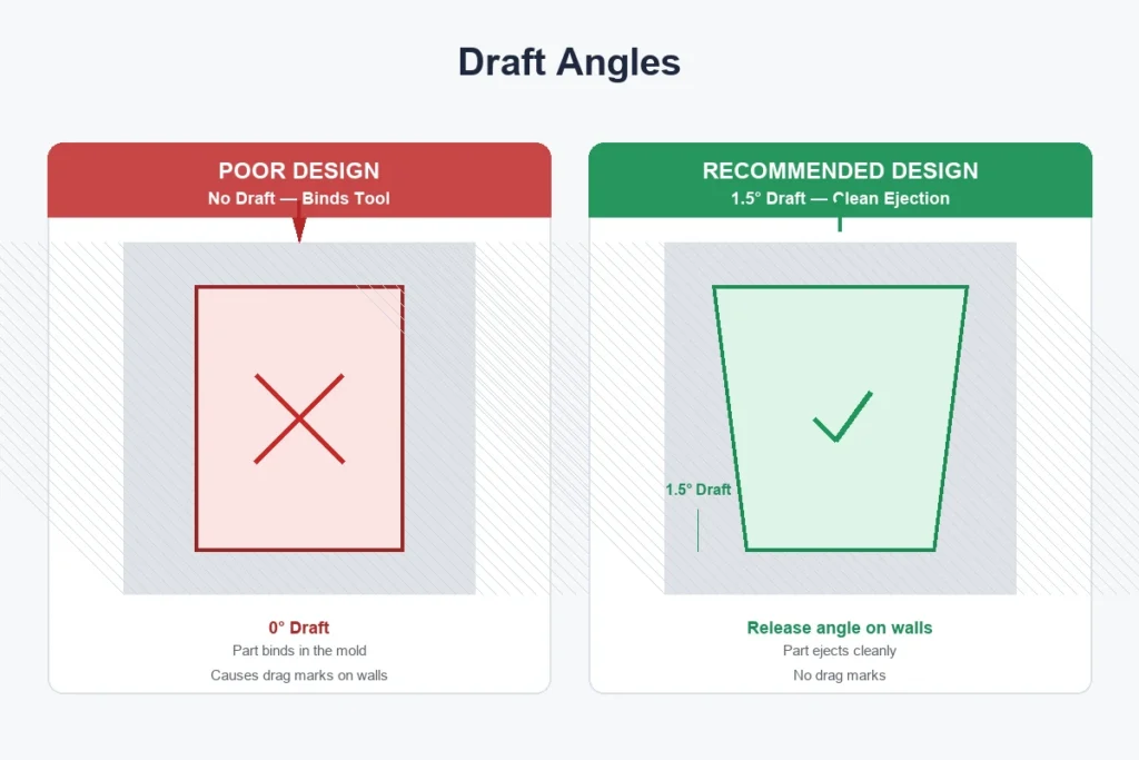
Incorporate a minimum draft angle of 1° to 2° per side. Textured surfaces require an extra 1° of draft for every 0.025 mm of texture depth to allow easy part ejection without drag marks.
Ribs and Bosses
Design rib thickness to 50–60% of the adjacent wall thickness to prevent sink marks on cosmetic faces. Base bosses with gussets to distribute mechanical loads.
Undercuts
Avoid undercuts to simplify mold construction. If undercuts are mandatory, use manual side-loads or automated side-action lifters.
Parting Lines
Position the parting line along flat outer edges to simplify mold split line sealing and minimize visible flash.
Gates and Runners
Select gate types based on resin viscosity and cosmetic needs. Edge gates work well for thick parts, while sub-gates auto-shear during ejection.
Cooling Channel Design
Position straight-drilled cooling channels 2 to 3 times their diameter away from cavity walls to maintain balanced thermal management across the core and cavity.
Shrinkage Considerations
Scale CAD geometry to compensate for volumetric material shrinkage—ranging from 0.4% for ABS to over 2.0% for semi-crystalline polymers like PP.
Tolerance Recommendations
Standard rapid tooling targets tolerances of ±0.005 inches (±0.125 mm). Tighter tolerances of ±0.002 inches (±0.05 mm) are achievable with finish CNC passes.
Rapid Tooling Design Checklist Before Manufacturing
CAD File Requirements
Submit clean 3D solid models in STEP or IGES formats alongside 2D PDF drawings indicating critical dimensions and thread callouts.
Material Selection Checklist
Verify that the chosen resin matches operational specs for tensile strength, heat deflection, UV exposure, and chemical compatibility.
Moldability Review
Run a formal DFM analysis to evaluate draft compliance, wall thickness variation, gate placement, and potential air traps.
Quality Control Considerations
Define critical-to-quality (CTQ) dimensions, required surface finish specs, and key inspection criteria before releasing the mold build.
Advantages of Rapid Tooling
Faster Time to Market
Slashing tool fabrication times allows product launches weeks ahead of competitors using traditional tooling routes.
Lower Development Costs
By using simplified modular mold frames and high-speed machining, overall initial tooling expenditures drop by 30% to 70%.
Faster Design Iterations
Modifying an aluminum mold insert takes days, enabling fast design iteration loops based on real test data.
Reduced Manufacturing Risk
Catch geometry flaws and assembly errors early using real molded parts before locking in high-volume tool designs.
Improved Product Validation
Run physical drop tests, thermal exposure, and regulatory certifications using true end-use plastics.
Related: Custom Metal 3D Printing Services: Materials, Pricing & Lead Times Explained
Limitations of Rapid Tooling
Mold Life
Softer mold materials like 7075 aluminum degrade faster than hardened tool steel under abrasive conditions or high clamping forces.
Production Volume Limits
Rapid tooling works best for short to medium production runs; high-volume orders running into hundreds of thousands of parts warrant fully hardened production tools.
Surface Finish Considerations
Hand-loaded inserts or printed tooling inserts can leave faint parting lines on finished plastic parts.
Material Compatibility
Abrasive, highly-filled materials (such as 40% glass-reinforced resins) rapidly wear unplated aluminum tooling cavities.
Rapid Tooling vs Traditional Tooling
Cost Comparison
Rapid Tooling: $2,000 – $15,000 initial investment.
Traditional Tooling: $25,000 – $100,000+ upfront capital.
Lead Time Comparison
Rapid Tooling: 1 to 3 weeks.
Traditional Tooling: 8 to 16 weeks.
Durability Comparison
Rapid aluminum tools typically last up to 50,000 cycles. Traditional steel tools easily endure over 1,000,000 cycles.
Production Volume Comparison
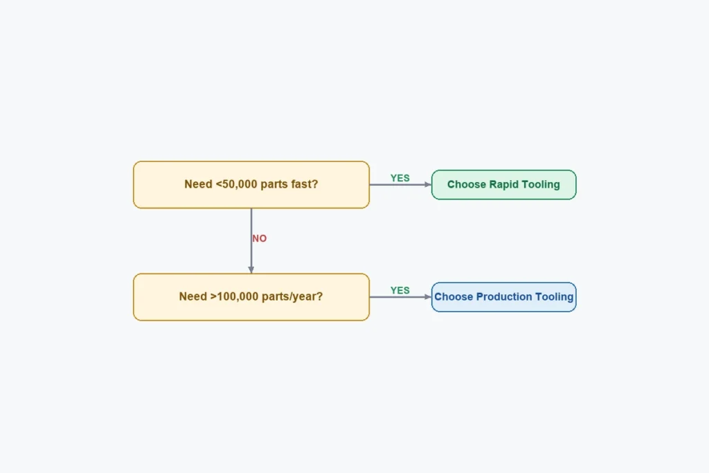
Choose rapid tooling for 50 to 50,000 units. Opt for traditional tooling for continuous mass production runs above 100,000 units.
Which Option Should You Choose?
Rapid Tooling vs 3D Printing
Speed
3D printing delivers 1 to 10 parts overnight. Rapid tooling takes 1 to 2 weeks for mold build, then produces hundreds of parts daily.
Cost
3D printing costs less for under 20 units. Above 50 units, rapid injection molding becomes more economical per part.
Material Options
Rapid tooling uses standard production polymers. 3D printing relies on specialized photopolymers or filaments that only mimic production resins.
Part Quality
Injection molded parts offer isotropic mechanical properties, consistent surface finishes, and superior cosmetic uniformity compared to 3D printed parts.
Best Applications
Use 3D printing for visual concept models; choose rapid tooling for functional testing, field trials, and low-volume sales.
Rapid Tooling vs CNC Machining
Manufacturing Workflow
CNC machining cuts every part from a solid block of plastic. Rapid tooling cuts the negative cavity once into metal, then injects plastic repeatedly.
Cost Comparison
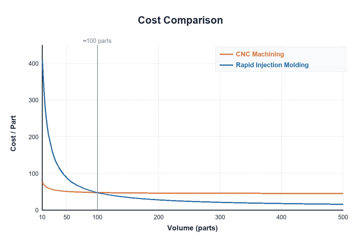
At 10 parts, direct CNC machining is usually cheaper. Above 100 parts, rapid tooling delivers lower unit costs.
Lead Times
Direct CNC machining delivers parts within days. Rapid tooling requires a week for mold build, then produces parts in seconds.
Typical Use Cases
Machining suits simple geometries or ultra-low quantities. Rapid tooling suits complex, thin-walled enclosures and larger part volumes.
Industries That Use Rapid Tooling
Automotive
Prototyping interior trim pieces, HVAC ducting, under-hood sensor housings, and custom aftermarket components.
Aerospace
Low-volume cabin interior fittings, duct connectors, and lightweight structural brackets.
Medical Devices
Producing ergonomic handles, enclosure housings, and fluidic manifolds using medical-grade ISO 10993 materials for clinical trials.
Consumer Electronics
Rapid iterations of handheld device casings, wear-tested bezels, and internal structural frames.
Industrial Equipment
Short-run replacement gears, protective shrouds, and custom assembly line jigs.
Robotics
Custom chassis frames, mounting plates, and lightweight structural covers.
Consumer Products
Limited-run athletic gear, kitchen appliances, and vanity packaging before full retail rollouts.
Applications of Rapid Tooling
Functional Prototypes
Evaluating mechanical snap-fits, living hinges, and structural loads using end-use materials.
Pilot Production
Testing line throughput, assembly workflows, and packaging designs while waiting for production tools.
Bridge Manufacturing
Fulfilling initial customer orders and generating cash flow while primary tooling is built.
End-Use Plastic Parts
Cost-effectively supplying niche markets requiring only a few thousand units annually.
Product Validation
Submitting physical parts to UL, CE, or FDA regulatory bodies for formal compliance testing.
Low-Volume Manufacturing
Supporting high-mix, low-volume product strategies without tying up capital in expensive tooling.
Related: Custom Overmolding Services: Design, Materials, Manufacturing & Pricing Guide (2026)
Quality Control in Rapid Tooling
Dimensional Inspection
CMM and 3D optical scanners measure critical features against the master CAD model, verifying compliance with tight tolerances.
Mold Testing
Evaluating mold performance during trial runs to optimize ejection forces, cooling consistency, and venting capability.
First Article Inspection (FAI)
Comprehensive FAI reports confirm part geometry, material density, and surface specifications prior to full batch production.
Process Validation
Monitoring temperature curves, injection pressure, and hold times to establish stable, repeatable mold parameters.
Production Consistency
Automated process logging ensures every injected shot matches the quality of the approved sample parts.
Common Rapid Tooling Challenges and How to Avoid Them
Poor Mold Design
Inadequate draft leads to scuff marks and part sticking.
Run early DFM reviews to enforce mandatory draft angles across all vertical surfaces.
Material Selection Mistakes
High material shrinkage causes warpage in unreinforced resins.
Perform mold flow analysis simulations during tool design to predict shrinkage patterns accurately.
Cooling Problems
Uneven cooling causes component distortion and long cycle times.
Integrate conformal or balanced straight-line cooling lines to keep cavity temperatures uniform.
Flash and Sink Marks
Excessive injection pressure creates flash, while overly thick sections cause sink.
Maintain consistent wall thicknesses and optimize packing pressure profiles.
Warpage
Differential cooling or internal stresses bend flat parts out of spec.
Balance cooling layout and adjust gate positions to ensure uniform fill patterns.
Short Shots
Plastic solidifies before completely filling the cavity.
Increase mold vent depth, raise melt temperatures, or enlarge gate land areas.
Rapid Tooling Cost Factors
Mold Complexity
Complex geometries requiring side-actions, lifters, or unscrewing mechanisms increase machining hours and initial rapid mold cost.
Mold Material
Aluminum inserts lower initial cutting costs; P20 or H13 steel inserts increase upfront material expense but offer longer tool life.
Number of Cavities
Single-cavity tools reduce upfront cost. Multi-cavity tools cost more to build but lower the per-part cost on larger runs.
Surface Finish Requirements
Standard machined finishes save money, while high-gloss diamond polishes or custom textures require extra hand work.
Production Quantity
Amortizing tooling costs over larger production runs lowers the net unit price of each finished part.
Secondary Operations
Post-processing needs like ultrasonic welding, pad printing, surface painting, or brass insert installation add to total assembly cost.
Related: Continuous Fiber 3D Printing: Reinforced Additive Manufacturing (2026)
Typical Lead Times for Rapid Tooling Projects
Prototype Tooling
- Lead Time: 5 to 10 Business Days
- Focus: Speed, basic functionality, fast design verification.
Bridge Tooling
- Lead Time: 2 to 3 Weeks
- Focus: Semi-automated production, durability, moderate volume supply.
Production Tooling
- Lead Time: 6 to 10 Weeks
- Focus: Fully automated multi-cavity hardened steel tools for mass production.
How Lava3DP Delivers Rapid Tooling Solutions
Design for Manufacturability (DFM) Support
Lava3DP provides expert DFM feedback within 24 hours. Our engineering team reviews gate placement, draft angles, wall thickness, and material flow to catch issues early.
CNC Machining for Mold Manufacturing
Using modern multi-axis CNC milling machines, we produce high-precision aluminum and tool steel mold inserts with tight tolerances and exceptional surface quality.
High-Precision 3D Printing Services
We offer metal DMLS and high-resolution SLA options to produce complex mold inserts, custom cooling geometries, and master patterns fast.
Rapid Injection Molding Solutions
Lava3DP provides scalable low-volume molding services, delivering real production parts in as little as 7 business days.
Material Selection Assistance
Our engineers help you select optimal materials from a range of engineering resins, including ABS, PC, Nylon, PEEK, and glass-filled compounds.
Quality Inspection and Production Support
Every run includes detailed FAI reports, CMM measurements, and resin certification tracking to ensure consistent quality.
Fast Global Manufacturing and Shipping
With automated workflows and international logistics networks, Lava3DP ships high-precision tooling and parts worldwide.
How to Order Custom Rapid Tooling from Lava3DP
Upload Your CAD Files
Visit the Lava3DP platform and upload your 3D CAD files (STEP, IGES, or STL) to request an online rapid tooling quote.
Receive a Design Review
Our engineering experts run a DFM analysis and send a detailed design feedback report along with cost options.
Confirm Materials and Manufacturing Process
Select your target resin, tool material (aluminum or steel), surface finish, and quantity.
Prototype and Tool Production
We machine your mold inserts, assemble the tool frame, and run initial T1 sampling shots.
Quality Inspection and Delivery
After verifying sample parts against your specifications, we complete production and ship your parts directly to your door.
Ready to Manufacturing with LAVA3dp?
Upload your CAD file today and receive instant pricing, expert engineering support, fast production, and worldwide delivery.
Get an Instant Quote →Frequently Asked Questions
What is meant by rapid tooling?
Rapid tooling is a manufacturing process that uses direct CNC machining, additive manufacturing, or pre-engineered mold bases to produce mold cavities and inserts quickly, slashing lead times compared to conventional mold making.
What is the difference between rapid tooling and rapid prototyping?
Rapid prototyping creates visual or functional models directly from CAD data (typically via 3D printing). Rapid tooling builds actual mold tooling that produces parts using real injection molding machines and production resins.
What is an example of rapid tooling?
A common example is cutting a 7075 aluminum mold cavity using high-speed CNC machining to produce 2,000 plastic enclosure parts in under two weeks.
What is the difference between rapid tooling and conventional tooling?
Rapid tooling uses aluminum or soft steel inserts, simplified mold frames, and speed-optimized machining to deliver parts in days or weeks. Conventional tooling uses fully hardened tool steel, complex cooling channels, and multi-cavity setups built to last millions of cycles over months of production.
What is the difference between rapid tooling and production tooling?
Rapid tooling focuses on low volumes, low upfront costs, and fast delivery for design validation or bridge production. Production tooling prioritizes maximum durability, multi-cavity automation, and low per-part costs for long-term mass manufacturing.
What materials are used for rapid tooling?
Common materials include 6061 and 7075 aluminum, P20 pre-hardened tool steel, H13 tool steel, stainless steel, and 3D-printed metal inserts (maraging steel).
How long does rapid tooling take?
Most rapid tooling projects take between 5 and 15 business days depending on part complexity, cavity count, and selected mold material.
Is aluminum tooling suitable for injection molding?
Yes. High-strength 7075-T6 aluminum makes exceptional injection molds. It offers excellent thermal conductivity, cuts machining times, and handles production runs up to 50,000 shots in non-abrasive resins.
What file formats are required for rapid tooling?
3D STEP (.step, .stp) and IGES (.iges, .igs) solid model formats work best for tool path generation and DFM analysis, alongside a 2D PDF drawing for critical dimensions and tolerances.