

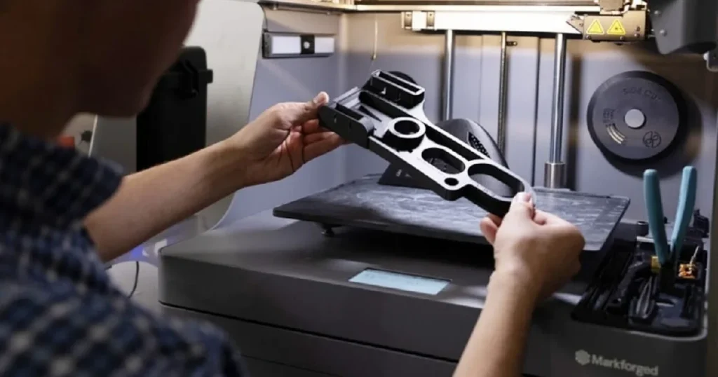
What Is Continuous Fiber 3D Printing?
Continuous Fiber 3D Printing—often referred to as Continuous Fiber Reinforcement (CFR)—is an advanced additive manufacturing technology that embeds long, unbroken strands of high-strength fibers (such as carbon fiber, fiberglass, or Kevlar) directly into a thermoplastic matrix during the printing process.
How Continuous Fiber Reinforcement Works
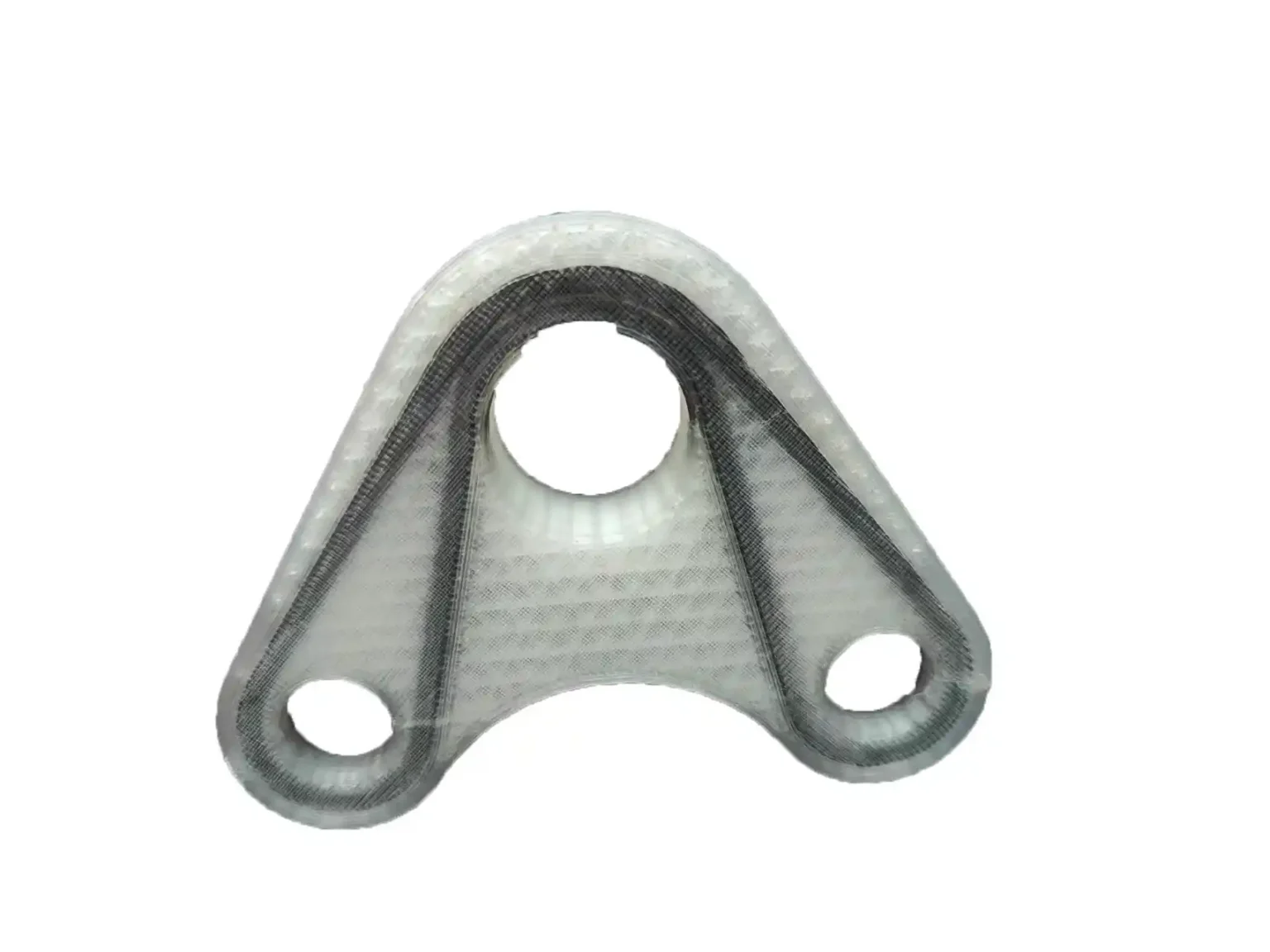
Unlike standard 3D printing that melts a single filament, CFR machines utilize a dual-nozzle system operating in sync:
- Matrix Nozzle: Lays down a high-performance thermoplastic base (e.g., micro-carbon fiber filled Nylon).
- Fiber Nozzle: Lays down continuous strands of structural fiber coated with a iron-clad binder, ironing them directly into the molten matrix layer along pre-programmed load paths.
Related: Continuous Fiber 3D Printing Service | Strong Composite Parts
Continuous Fiber vs. Chopped Carbon Fiber Reinforcement
Chopped Carbon Fiber Filament
Chopped Carbon Fiber Filament: Short, microscopic fibers scattered randomly throughout plastic pellets or spools. Adds rigidity and dimensional stability, but tensile strength remains bound by the plastic.
Continuous Fiber
Continuous Fiber: Long, uninterrupted strands laid continuously across the stress vectors of the part. This creates a true composite structure where tensile loads are transferred along the full length of the fiber—yielding up to 20x the tensile strength of standard filaments.
Why Continuous Fiber 3D Printing Is Different from Conventional FDM
Standard Fused Deposition Modeling (FDM) relies purely on polymer chain entanglement, making isotropic strength impossible and limit layer-to-layer bond integrity. CFR bridges the gap between FDM speed and industrial composite layups, turning printed parts into functional, structural replacements for CNC-machined metal.
Key Benefits of Reinforced Additive Manufacturing
- Unrivaled Strength-to-Weight Ratio: Yield strengths matching 6061-T6 Aluminum at a fraction of the mass.
- Targeted Reinforcement: Place fiber only where FEA (Finite Element Analysis) shows high stress, saving material and weight.
- Zero Tooling Costs: Skip complex compression molding dies or multi-axis CNC setups.
- Rapid Metal Replacement: Produce functional jigs, fixtures, and end-use components in 24–48 hours.
How the Continuous Fiber 3D Printing Process Works
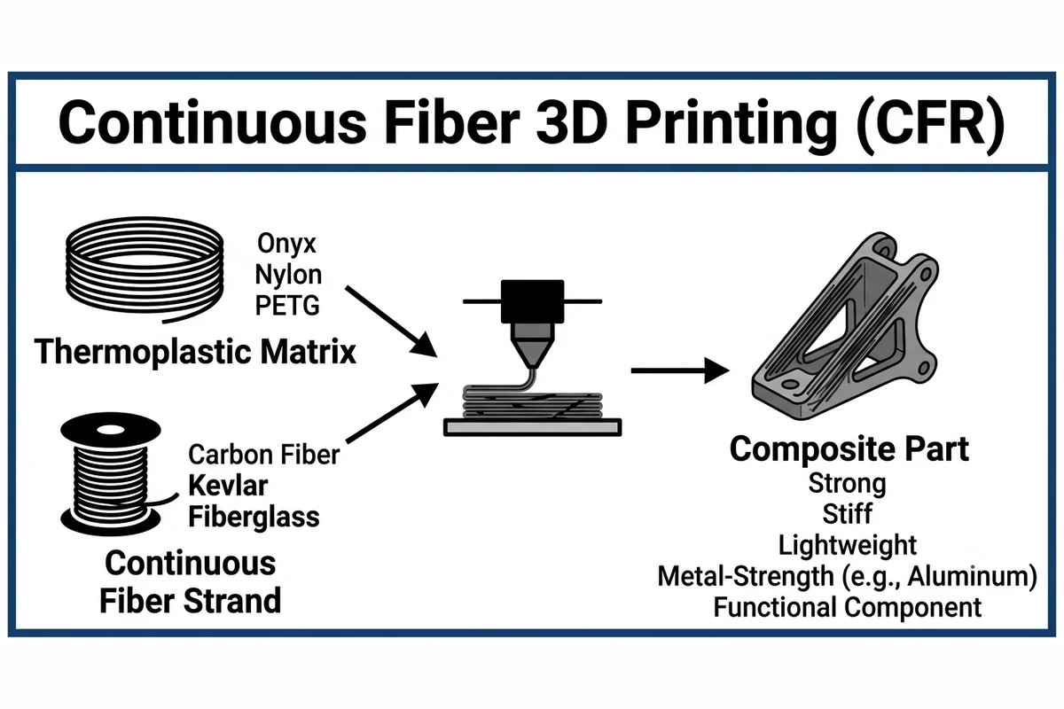
CAD Design and Design for Additive Manufacturing (DfAM)
The process begins with a 3D CAD model (STEP or IGES format). During the DfAM stage, engineers evaluate wall thickness, rib orientations, and pin/bolt locations to leverage anisotropic fiber paths effectively.
Material Selection Based on Mechanical Requirements
Engineers pair a ductile or heat-resistant base resin (like Nylon, Onyx, or PEEK) with a structural fiber strand matched to operational stress (e.g., Carbon Fiber for raw stiffness, Kevlar for impact damping).
Fiber Placement and Reinforcement Strategies
Slicing engines map out fiber routing strategies based on expected forces:
- Concentric Reinforcement: Traces outer/inner perimeters to resist bending, twisting, and edge impacts.
- Isotropic Reinforcement: Lays down parallel fiber hatches at changing angles (0°, 45°, 90°, …) on selected horizontal layers, creating quasi-isotropic strength similar to traditional carbon fiber sheet layups.
Printing, Post-Processing, and Quality Inspection
After toolpath generation, dual-extrusion hardware executes the print. Once completed, parts undergo support removal, surface refinement, CNC secondary alignment (if tight tolerances are required), and dimensional verification via CMM/3D scanning.
Related: Rapid Prototyping Guide (2026): Processes, Materials & Costs
Continuous Fiber Reinforcement Materials
| Fiber Type | Key Characteristic | Tensile Strength | Flexural Modulus | Typical Applications |
|---|---|---|---|---|
| Continuous Carbon Fiber | Highest Strength & Stiffness | ~800 MPa | ~60 GPa | Metal replacement, robotic arms, structural brackets |
| Continuous Fiberglass | Cost-Effective Stiffness | ~590 MPa | ~22 GPa | General tooling, non-conductive fixtures, housings |
| HSHT Fiberglass | High Temp & High Impact | ~600 MPa | ~21 GPa | Mold inserts, engine bays, high-heat fixtures |
| Kevlar (Aramid) | Maximum Energy Absorption | ~600 MPa | ~27 GPa | Soft-touch jaws, crash components, wearing surfaces |
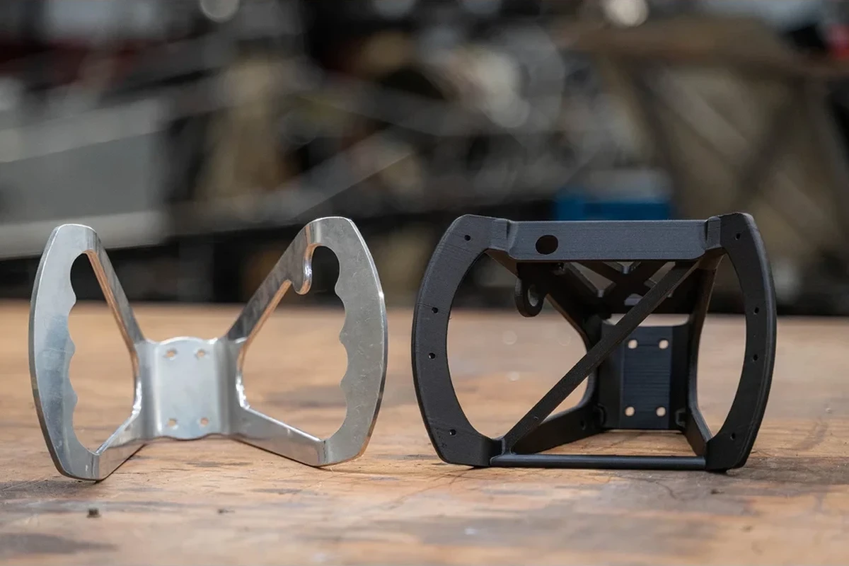
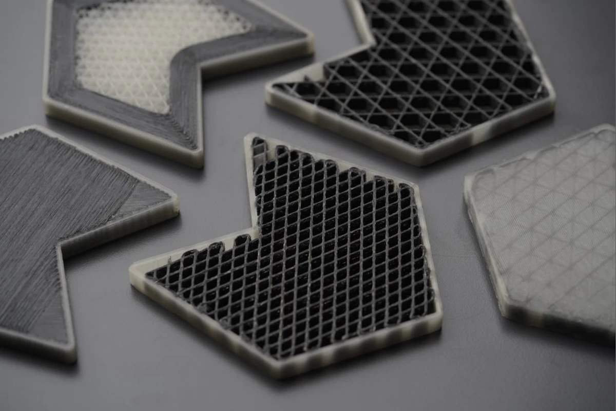
Continuous Carbon Fiber
Offers the highest strength-to-weight ratio of any printable composite material. It delivers tensile strength exceeding 6061-T6 Aluminum, making it ideal for high-stress structural parts requiring extreme rigidity.
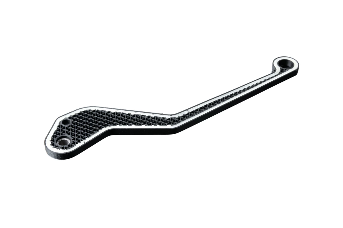
Continuous Fiberglass
An economical entry point for high-strength prints. Provides roughly 11x the stiffness of standard ABS, making it perfect for daily manufacturing jigs and assembly fixtures where raw carbon fiber stiffness isn’t required.
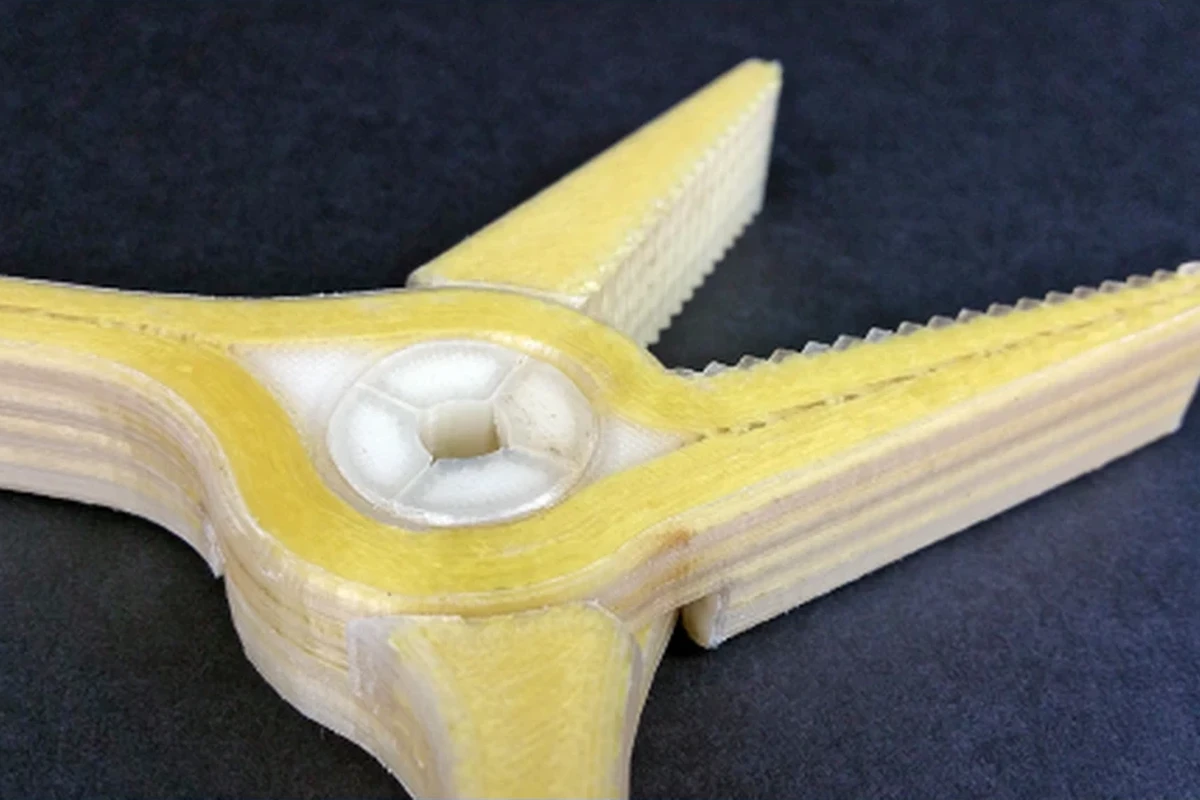
High-Strength High-Temperature (HSHT) Fiberglass
Delivers the structural benefits of fiberglass alongside elevated deflection temperatures (150°C+ testing envelope). Ideal for autoclave tooling, thermoforming dies, and high-heat automotive applications.
Kevlar (Aramid Fiber)
Extremely ductile and impact-resistant. Kevlar yields before catastrophic failure, making it ideal for components subjected to intermittent shocks, heavy friction, or abrasive force.
Base Thermoplastic Matrices
Onyx: Micro-carbon fiber filled Nylon offering smooth surface finish, chemical resistance, and heat stability.
Nylon / PETG: High toughness and low friction coefficients.
Engineering Polymers (PEEK / PEKK): High-temperature options for demanding aerospace and oil & gas environments.
Choosing the Right Fiber for Your Application
For maximum stiffness & minimum deflection -> Carbon Fiber
For impact resistance & smooth wear -> Kevlar
For budget-friendly structural strength -> Fiberglass
For high-heat operating zones -> HSHT Fiberglass / PEEK Matrix
Continuous Fiber 3D Printing Capabilities
- High Strength-to-Weight Ratio: Lighten structural assemblies by up to 50–70% compared to aluminum.
- Lightweight Structural Components: Ideal for end-effectors and drone frames where lower mass yields higher speeds and longer battery life.
- Excellent Stiffness and Rigidity: Negligible flex under continuous load.
- Wear and Fatigue Resistance: Long cycle lifetimes in repeated friction or reciprocating movement setups.
- Chemical and Corrosion Resistance: Inherently impervious to oils, greases, cutting fluids, and many solvents.
- Heat Resistance for Industrial Environments: Maintains structural integrity under elevated ambient temperatures.
- Functional End-Use Parts: Directly deployable without secondary casting or machining steps.
Advantages of Continuous Fiber 3D Printing
| Material | Density (g/cm³) | Mass % (vs. Steel) | Indicator |
|---|---|---|---|
| Steel | 7.8 | 100% | |
| Aluminum | 2.7 | 35% | |
| Carbon CFR | 1.4 | 18% |
- Reduce Weight Without Sacrificing Strength: Slash part mass while handling structural loads.
- Replace Metal Components: Eliminate long lead-time CNC aluminum or steel parts.
- Faster Product Development: Turn multi-week tooling quotes into next-day production runs.
- Lower Manufacturing Costs: Save on material waste (subtractive vs. additive) and machine time.
- Tool-Free Production: No custom dies, workholding jigs, or specialized cutters needed.
- Rapid Design Iteration: Update CAD models, re-slice, and print overnight.
- Complex Geometry Manufacturing: Create organic internal lattice structures and internal wire channels impossible to cut on a CNC mill.
Related: Micro SLA 3D Printing: Technology, Materials, Accuracy, Applications & Cost Guide
Limitations and Design Considerations
Design Tip: Continuous fiber behaves like a rope—it works exceptionally well in tension, but cannot be laid in zero-radius corners.
Fiber Routing Constraints
Fiber cannot be squeezed into wall thicknesses thinner than ~1.5–2.0 mm, nor can it turn sharp 90° internal corners. Radii of at least 3 mm are recommended for smooth continuous routing.
Build Volume Limitations
CFR machines generally feature moderate build volumes compared to large-format commodity plastics. Larger assemblies are typically designed as modular, interlocking components.
Anisotropic Mechanical Properties
Strength is concentrated along the X-Y plane where the fiber is laid. Z-axis (layer-to-layer) strength relies on the base matrix resin, requiring thoughtful part orientation.
Surface Finish Expectations
Outer perimeters show a clean matte or satin finish (especially with Onyx base resins), but internal fiber-layer boundaries can produce distinct internal layer textures.
Design Guidelines for Maximum Strength
- Orient Primary Loads in X-Y: Rotate CAD geometry so tensile and bending forces run parallel to the build plate.
- Use Sandwich Panels: Place continuous fiber layers on the top and bottom faces of the part, with lightweight infill in the middle (mimicking an I-beam structure).
- Maintain Smooth Contours: Avoid jagged contours to maximize continuous fiber path lengths.
Continuous Fiber vs. Other Manufacturing Technologies
| Technology | Lead Time | Part Strength | Weight | Initial Tooling Cost |
|---|---|---|---|---|
| Continuous Fiber (CFR) | 1–3 Days | Very High | Ultra-Light | $0 |
| Chopped Filament FDM | 1–2 Days | Moderate | Light | $0 |
| CNC Machining (6061 Al) | 5–15 Days | Extremely High | Medium | Moderate (Fixture setup) |
| Aluminum Casting | 4–8 Weeks | Very High | Medium | High (Molds) |
| Injection Molding | 6–10 Weeks | Moderate-High | Light-Medium | Very High (Tooling) |
| DMLS (Metal 3D Printing) | 3–7 Days | Extremely High | Heavy-Medium | $0 (High part unit cost) |
Continuous Fiber vs. Carbon Fiber Filled Filament
Filled filaments offer stiffness, but CFR offers structural strength capable of handling continuous mechanical loading.
Continuous Fiber vs. CNC Machining
CNC offers higher Z-axis isotropy and surface finish precision, but CFR slashes lead times, eliminates material waste, and reduces part mass by 40–60%.
Continuous Fiber vs. Metal 3D Printing (DMLS / SLM)
DMLS is suited for extreme thermal environments ($>300^\circ\text{C}$), but CFR delivers comparable strength at a fraction of the cost, weight, and post-processing requirement.
Mechanical Properties Comparison
| Material | Tensile Strength (MPa) | Indicator |
|---|---|---|
| Standard ABS | 35 | |
| Chopped Onyx | 40 | |
| 6061-T6 Aluminum | 310 | |
| Continuous Carbon Fiber | 800 |
- Tensile Strength: Up to 800 MPa with continuous carbon fiber (higher than structural steel).
- Flexural Strength: Up to 540 MPa, enabling parts to flex without cracking or permanent deformation.
- Impact Resistance: Kevlar reinforcement provides energy absorption above 260 J/m.
- Stiffness (Young’s Modulus): Up to 60 GPa, keeping critical components rigid under load.
- Fatigue Performance: Minimal creep and structural degradation over millions of strain cycles.
Applications and Industries Served
Applications
- Aerospace: Lightweighted ducting brackets, drone arms, interior mounting fixtures, UAV chassis.
- Automotive: Custom racecar brackets, intake manifolds, sensor mounts, chassis bracing.
- Robotics & Automation: Lightweight end-of-arm tooling (EOAT), gripper fingers, robotic joint housings.
- Industrial Tooling & Fixtures: Soft jaws, CMM inspection fixtures, welding jigs, assembly aids.
- Medical & Defense: Ergonomic orthotic frames, ruggedized communications enclosures, field-ready replacement hardware.
Industries Served
Aerospace & Defense · Automotive & Motorsports · Industrial Automation · Medical Devices · Energy & Marine · Higher Education & R&D Laboratories.
Related: Full Color 3D Printing Services: Technologies, Pricing & Design Guide (2026)
Surface Finishes and Post-Processing
Support Removal
Support Removal: Manual precision removal of soluble or breakaway support structures.
Sanding and Surface Smoothing
Sanding and Surface Smoothing: Progressive wet/dry sanding for tight dimensional interfaces.
CNC Secondary Machining
CNC Secondary Machining: Precision reaming of pin holes, milling of sealing faces, and tapping threads to ±0.02 mm tolerances.
Hardware Installation
Hardware Installation: Heat-set brass thread inserts, press-fit bushings, and helicoils for robust threaded connections.
Quality Assurance & Manufacturing Standards
- Material Traceability: Full lot tracking on matrix spools and continuous fiber spools.
- Engineering Design Review: Every CAD file is vetted for fiber continuity, hole clearances, and stress orientation before slicing.
- Dimensional Inspection: Verified with digital calipers, optical comparators, or 3D laser scanners.
- Mechanical Verification: Periodic destructive testing to validate inter-layer bond strength and fiber adhesion.
Why Choose Lava3DP for Continuous Fiber 3D Printing
Continuous fiber 3D printing requires more than just advanced equipment. Successful projects depend on material selection, part orientation, fiber reinforcement strategy, dimensional accuracy, and quality control throughout production. Lava3DP combines industrial additive manufacturing expertise with engineering support to help customers produce lightweight, high-strength composite parts for functional applications.
Instant Online Quoting
Lava3DP provides an online quotation platform that allows you to upload your CAD files and receive pricing within minutes. This helps engineers and product developers compare manufacturing options quickly, estimate project budgets, and start production without long quotation delays.
Engineering and DFM Support
Every project is reviewed by experienced manufacturing engineers before production begins. Our Design for Manufacturing (DFM) support helps optimize wall thickness, reinforcement paths, print orientation, tolerances, and material selection to improve strength while reducing unnecessary production costs. If improvements are possible, our engineering team provides practical recommendations before manufacturing starts.
Wide Range of Manufacturing Technologies
Some parts are better suited for continuous fiber reinforcement, while others may benefit from CNC machining, SLS, SLA, MJF, DMLS, or traditional manufacturing processes. Lava3DP offers multiple manufacturing technologies through a single platform, allowing customers to choose the most suitable solution based on strength requirements, material properties, lead time, and budget.
High-Performance Composite Materials
We manufacture parts using engineering-grade composite materials reinforced with continuous carbon fiber, fiberglass, HSHT fiberglass, and Kevlar. Depending on the application, we also offer high-performance thermoplastics such as Onyx, Nylon, PETG, PEEK, and PEKK to achieve the required balance of strength, heat resistance, wear resistance, and weight reduction.
Fast Lead Times
Compared with conventional manufacturing methods that often require tooling or extensive machining, continuous fiber 3D printing significantly reduces production time. Most prototype and low-volume production orders can be manufactured within just a few days, helping accelerate product development and reduce time to market.
Prototype to Production Capability
Whether you need a single prototype, engineering validation parts, bridge production, or low-volume manufacturing, Lava3DP supports projects throughout the entire product development cycle. Our manufacturing workflow allows customers to move from concept to production without changing suppliers.
Global Manufacturing and Shipping
Lava3DP serves customers worldwide by combining digital manufacturing with reliable international logistics. Finished parts are carefully inspected, securely packaged, and shipped globally, allowing engineering teams to receive production-quality components wherever they are located.
How to Order Continuous Fiber 3D Printed Parts from Lava3DP
Ordering custom composite parts through Lava3DP is designed to be simple and efficient. From quotation to delivery, every stage focuses on ensuring your parts meet performance, quality, and dimensional requirements.
Upload Your CAD File
Begin by uploading your 3D CAD model using the Lava3DP online quotation platform. Common file formats such as STEP, STP, STL, OBJ, and other standard CAD formats are supported. Providing accurate design files helps speed up engineering review and manufacturing preparation.
Receive an Instant Quote
After uploading your design, you receive an instant manufacturing quotation based on your selected material, dimensions, quantity, and production requirements. This provides transparent pricing before production begins.
Design Review and Material Recommendation
Our engineering team reviews each design for manufacturability. Based on your application’s mechanical requirements, we recommend suitable reinforcement fibers, base thermoplastics, print orientation, and reinforcement strategies to maximize performance while maintaining cost efficiency.
Production and Quality Inspection
Once the design is approved, production begins using industrial manufacturing equipment. Every component undergoes dimensional inspection and quality verification before shipment to ensure it meets specified manufacturing requirements.
Worldwide Delivery
After final inspection, parts are securely packaged and shipped to customers worldwide. Tracking information is provided so you can monitor your shipment from production to delivery.
Continuous Fiber 3D Printing Cost
The cost of continuous fiber 3D printing depends on several manufacturing variables rather than a fixed price per part. Understanding these factors helps you optimize both performance and production cost.
Factors That Affect Pricing
Several technical and production considerations influence manufacturing costs, including material selection, fiber reinforcement level, part size, geometry, production quantity, printing time, and post-processing requirements. Complex parts requiring additional reinforcement or finishing generally cost more than simple geometries.
Material Selection
Different composite materials vary in price and performance. Continuous carbon fiber typically offers the highest mechanical performance, while fiberglass provides a more economical solution for many structural applications. Engineering polymers such as PEEK and PEKK generally increase manufacturing costs because of their specialized processing requirements.
Fiber Volume and Reinforcement Density
The amount of continuous fiber embedded within a part directly affects both mechanical performance and material consumption. Components with higher reinforcement density provide greater strength and stiffness but require more fiber material and longer production times.
Part Size and Geometry
Larger parts require more raw material and longer printing times. Highly complex geometries, thin walls, internal channels, tight tolerances, and intricate reinforcement paths may also increase manufacturing time and overall production cost.
Quantity and Production Scale
Single prototype parts generally have the highest unit cost. Producing multiple identical components improves manufacturing efficiency, reducing the cost per part for low- and medium-volume production runs.
Tips to Reduce Manufacturing Costs
You can often reduce manufacturing costs without sacrificing performance by simplifying unnecessary design features, reducing excess material, selecting the most appropriate reinforcement material, minimizing support structures, combining multiple revisions into a single production run, and consulting with manufacturing engineers early during the design process. Design optimization before production frequently results in both lower costs and better-performing parts.
Ready to Manufacturing with LAVA3dp?
Upload your CAD file today and receive instant pricing, expert engineering support, fast production, and worldwide delivery.
Get an Instant Quote →Frequently Asked Questions
Can you 3D print continuous carbon fiber?
Yes. Continuous carbon fiber is co-extruded through a specialized secondary nozzle, embedding full strands of fiber inside molten thermoplastic during the print process.
What is a continuous fiber 3D printer?
A continuous fiber 3D printer features dual extrusion heads—one for laying down a base thermoplastic matrix (like Nylon or Onyx) and a dedicated ironing head that routes continuous fiber strands into the part along specified load paths.
Is continuous fiber stronger than carbon fiber filament?
Yes, significantly stronger. Carbon fiber filament contains short, chopped fibers mixed into plastic, which adds stiffness but offers limited tensile improvement. Continuous fiber uses long, unbroken strands, yielding up to 20x the tensile strength of chopped filaments.
What base materials can be reinforced with continuous fiber?
Common base thermoplastics include Onyx (micro-carbon filled Nylon), pure Nylon, PETG, ABS, and high-performance polymers like PEEK and PEKK.
What industries benefit most from CFR technology?
Aerospace, automotive, robotics, and contract manufacturing benefit most by using continuous fiber parts to replace CNC-machined aluminum fixtures, end-effectors, and structural brackets.
How does continuous fiber 3D printing cost compare to metal CNC machining?
For low-to-medium volumes (1–100 parts), continuous fiber 3D printing is typically significantly cheaper and faster than CNC machining because it eliminates setup fees, specialized workholding, and expensive multi-axis machine time.